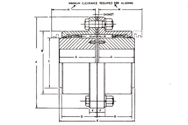
Full Gear type AFG Allflex Flexible Gear Coupling consists of two identical toothed hubs, two identical flanged sleeves with internal teeth, a flange gasket, a set of flange bolts nuts and lockwashers, four lube plugs with Alluminium gaskets and two oil/grease retaining Nitrile ‘O’ rings over the hubs.
For couplings upto size 110 flanged sleeves are made from closed die forgings and hubs from EN9/C55 steel. For the bigger couplings the sleeves are made from grade 1 cast steel and hubs from forged steel.
The flanged sleeves are identical and interchangeable and are connected with each other by means of tight fitting close tolerance bolts in jig drilled and jig reamed flange bolt holes.
The use of ‘O’ rings for sealing of oil/grease eliminates the necessity of dismantling the hubs from shafts for changing the oil retaining ‘O’ rings.
The specification sheets give the maximum .torque, bore and RPM capacities of individual couplings. To arrive at final size please adopt the following procedure :
1. Calculate the Effective Torque to be transmitted from following formula:
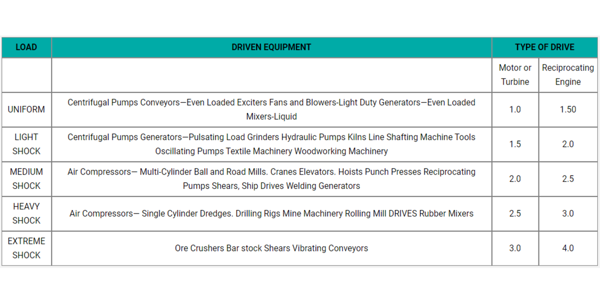
Where SF is the service factor to be selected from shown table.
2. Select the coupling size tentatively on the basis of bore considering the maximum diameter of driven and driving shafts. In case the rated torque capacity of coupling thus selected is equal or more to the effective torque calculated above, confirm the coupling size. In case the rated. torque, is less than effective torque, increase coupling to the size with rated torque equal or more than the effective torque.
3. mCheck that the RPM of coupling is within limits of maximum RPM specified for the size of coupling selected. In case of higher RPMs refer the matter to us for special High speed couplings which are dynamically balanced.
RECOMMENDED SERVICE FACTORS (S.F.)
In order to provide for the dynamic torque which must be transmitted, it may be necessary to increase the horsepower to be transmitted by a factor which will allow for momentary increases in torque due to the characteristics of the equipment. The service factors shown in the table below provide a basis for estimating this allowance for specific combinations of connected equipment.
These factors are derived from long experience with average applications and they are to be considered as a general guide. For conditions not covered by the table, good judgement must be exercised and a factor selected by referring to the type of equipment most closely approximating the type of application being considered. In case of doubt please refer the matter to us.